|
||||||

Protype Tubing Components
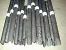
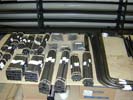
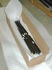
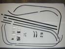
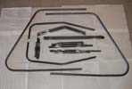
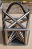
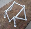
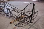
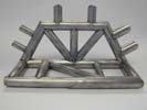
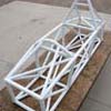
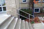

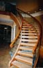

Tubing Kits, ‘ready to weld’ out of the box !!!
Suggestions for 3D Solid Modeling of Tube Structures
This document is to assist designers in preparing information suitable for our tube profiling process.
These methods and suggestions should be compatible with most 3D solid modeling packages.
- Our tube fabrication team is most familiar with ‘Solidworks’ software and produces tube structure as a
‘weldment’ part file. Some advantages are:
- one file contains the complete parametric information and therefore can be sent without related attachment files or libraries
- trim and extend features are quick and easy
- profile library of tube sizes is convenient
- one file to update with any changes to tube sizes or geometry
- Each structure starts by establishing an initial reference plane. This plane is usually through the centerline of the structure. This establishes the profile of the structure.
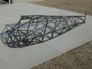
- Create a 3D wire frame representing the tube centerlines of the major structural tubes ensuring the parametric features are fully defined as the structure grows
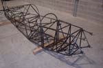
- Build the tube structure on the solid model generally in the same order as one would build the structure on the shop floor
- Add the tubes with the correct od and wall thickness and extrude along the lines and curves. Do not combine lines and paths into one solid body until the structure is complete. The trimming features are generally more reliable this way.
- Trim/extend or cut/extrude each tube as it is added to the existing tubes in the structure. This is less confusing than determining the trim sequence with all tubes in the structure.
- Ensure the parametric design features and geometry are fully defined as you proceed.
- Avoid ‘mirroring’ tubes. Mirrored tubes generally have unique profile paths and require separate profile programs to produce. Trim features are more robust. Changes are easier to apply downstream.
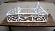
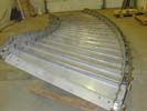
- Once all the tubes in the solid model are added and trimmed, combine the tube segments as required to produce single tube components. This applies mostly to curved, formed or bent tubes.
- Assign each tube in the solid model a unique part number. Using ‘solidworks’, this is done in the cutlist.
- At this point, the 3D model is just a ‘cartoon’. The required information to produce this structure is not readily accessible or organized and the dimensional design cannot be checked easily.
- An assembly drawing with material list must be created to itemize the number of pieces. Create a drawing with an isometric view, bill of material and add balloons for each tube component.
- Create a drawing with the 3 main views (side, front, top) plus any important section views. Add overall dimensions, station dimensions and layout dimensions to verify the design configuration. These dimensions will also be required to assemble and build the tube structure on the shop floor.
- Review and check the design:
- confirm the design dimensions
- confirm tube sizes
- confirm all tubes are shown
- review all trims at tube clusters
- Confirm that bend radii and tube sizes are compatible with available bending dies and manufacturing procedures.
- Produce a part file for each tube in the weldment maintaining the parametric link to the solid model weldment.
- Open each part file for the round straight tubes. Visually check the end trims to confirm complete end trims. Then, insert a new or temporary coordinate system such that the ‘z’ axis is aligned with the primary axis of the tube. Locate the coordinate vertex anywhere between the 2 ends. Point the positive ‘z’ direction toward the tube end with the ‘most complex’ profile. Save this file in ‘iges’ format which will no longer have a parametric link to previous files. This file must represent a single solid body.
- Square tubes require an additional step to round tubes. Also align the ‘x’ and ‘y’ axis perpendicular to the faces of the square tube profile.
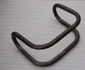
- Tubes with Bends:
Send the formed tubes as an iges file without adding a new coordinate system and accompany this with a drawing file. VR3 will import this into solidworks, ‘straighten’ the tube while maintaining the profile orientations, adjust the length to suit bend allowances, profile the tube and then bend the tube into the final shape. Please review bend features with us prior to approving the final design to ensure compatability with bend dies and manufacturing procedures. - Send the iges files and material list to us for manufacturing the profiled tubes. From this file we can extract the profile data and generate the cnc tool path for the tube profiler.
- We will profile, label, package and send a set of tubes ready for weld assembly
Notes:
Feathered faces: Our tube profiling process always cuts the tube perpendicular to the tube surface. Our
programming path will eliminate the ‘feathered’ edges which result from 3d modelling. This
perpendicular cut to the surface is ideal for welding and results in a complete tube to tube contact
around the perimeter.